5
5 - 174
For price, delivery, and to place orders, please contact Hittite Microwave Corporation:
20 Alpha Road, Chelmsford, MA 01824 Phone: 978-250-3343 Fax: 978-250-3373
Order On-line at www.hittite.com
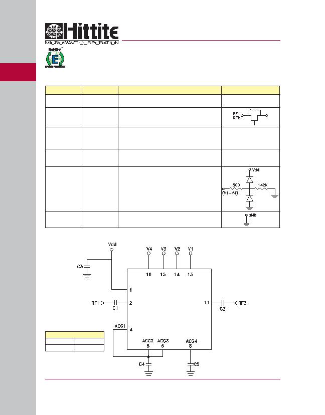
Pin Descriptions
Pin Number
Function
Description
Interface Schematic
1
Vdd
Supply Voltage.
2, 11
RF1, RF2
This pin is DC coupled and matched to 50 Ohm.
Blocking capacitors are required.
Select value based on lowest frequency of operation.
3, 7, 9, 10, 12
N/C
These pins should be connected to PCB RF ground to
maximize performance.
4 - 6, 8
ACG1 - ACG4
External capacitor to ground is required. Select value for
lowest frequency of operation. Place capacitor as close
to pins as possible.
13 - 16
V1 - V4
See truth table and control voltage table.
GND
Package bottom has an exposed metal paddle that must be
connected to RF/DC Ground.
Application Circuit
HMC540LP3 / 540LP3E
1 dB LSB GaAs MMIC 4-BIT DIGITAL
POSITIVE CONTROL ATTENUATOR, DC - 5.5 GHz
v00.0605
Recommended Component Values
C1 - C3
1,000 pF ?10%
C4, C5
330 pF ?10%
发布紧急采购,3分钟左右您将得到回复。
相关PDF资料
HMC542ALP4E
ATTENUATOR DGTL 6BIT 4X4QFN
HMC624LP4E
ATTENUATOR DGTL 6BIT 24QFN
HMC973LP3E
ATTENUATOR VOLT VARIABLE 16QFN
HRN-0118
ANTENNA HORN 1GHZ - 18GHZ
HYPERLOG30180
ANTENNA LOG 380MHZ-18GHZ
HYPERLOG4060
ANTENNA LOG 400MHZ-6GHZ
HYPERLOG60100
ANTENNA LOG 680MHZ-10GHZ
HYPERLOG7060
ANTENNA LOG 700MHZ-6GHZ
相关代理商/技术参数
HMC540LP3ETR
制造商:Hittite Microwave Corp 功能描述:ATTENUATOR DGTL 4BIT 3X3QFN 制造商:Hittite Microwave Corp 功能描述:HMC540 Series DC - 5.5 GHz GaAs MMIC 4-Bit Digital Attenuator - QFN-16
HMC540SLP3E
功能描述:RF Attenuator 15dB ±0.5dB 100MHz ~ 8GHz 16-VFQFN Exposed Pad 制造商:analog devices inc. 系列:- 零件状态:有效 衰减值:15dB 容差:±0.5dB 频率范围:100MHz ~ 8GHz 功率(W):- 阻抗:- 封装/外壳:16-VFQFN 裸露焊盘 标准包装:1
HMC540SLP3ETR
功能描述:ATTENUATOR DGTL 4BIT 16QFN 制造商:analog devices inc. 系列:- 零件状态:在售 衰减值:15dB 频率范围:100MHz ~ 8GHz 功率(W):- 封装/外壳:16-VFQFN 标准包装:1
HMC541LP3
制造商:HITTITE 制造商全称:Hittite Microwave Corporation 功能描述:10 dB GaAs MMIC 1-BIT DIGITAL POSITIVE CONTROL ATTENUATOR, DC - 5.0 GHz
HMC541LP3_08
制造商:HITTITE 制造商全称:Hittite Microwave Corporation 功能描述:10 dB GaAs MMIC 1-BIT DIGITAL POSITIVE CONTROL ATTENUATOR, DC - 5 GHz
HMC541LP3E
制造商:Hittite Microwave Corp 功能描述:IC ATTENUATOR DC-5GHZ 16-QFN
HMC541LP3ETR
制造商:Hittite Microwave Corp 功能描述:HMC541 Series DC - 5 GHz Digital Positive Control Attenuator - 3x3 mm QFN-16 制造商:Hittite Microwave Corp 功能描述:NA ONLY -HMC541 Series DC - 5 GHz Digital Positive Control Attenuator - QFN-16
HMC542ALP4
制造商:HITTITE 制造商全称:Hittite Microwave Corporation 功能描述:0.5 dB LSB GaAs MMIC 6-BIT DIGITAL SERIAL CONTROL ATTENUATOR, DC - 4 GHz
